
To access this section, follow the steps below:
Access the web interface of your switch. For instructions, click here.
Step 2:
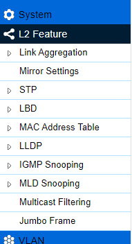
Click on L2 Feature.
Step 3:
The following settings can be configured under L2 Feature.
Link Aggregation
Mirror Settings
STP
LBD
MAC Address Table
LLDP
IGMP Snooping
MLD Snooping
Multicast Filtering
Jumbo Frame
Step 4:
Click Apply to update the system settings.
Link Aggregation
A Link Aggregation Group (LAG) optimizes port usage by linking a group of ports together to form a single, logical, and higher-bandwidth link. Aggregating ports multiplies the bandwidth and increases port flexibility for the switch. Link Aggregation is most commonly used to link a bandwidth intensive network device (or devices), such as a server, to the backbone of a network.
The participating ports are called Members of a port trunk group. Since all ports of the trunk group must be configured to operate in the same manner, the configuration of the one port of the trunk group is applied to all ports of the trunk group. Thus, you will only need to configure one of any of the ports in a trunk group. A specific data communication packet will always be transmitted over the same port in a trunk group. This ensures the delivery of individual frames of a data communication packet will be received in the correct order. The traffic load of the LAG will be balanced among the ports according to Aggregate Arithmetic. If the connections of one or several ports are broken, the traffic of these ports will be transmitted on the normal ports to guarantee the connection reliability.
When you aggregate ports, the ports and LAG must fulfill the following conditions:
- All ports within a LAG must have the same media/format type.
- A VLAN is not configured on the port.
- The port is not assigned to another LAG.
- The Auto-negotiation mode is not configured on the port.
- The port is in full-duplex mode.
- All ports in the LAG have the same ingress filtering and tagged modes.
- All ports in the LAG have the same back pressure and flow control modes.
- All ports in the LAG have the same priority.
- All ports in the LAG have the same transceiver type.
- Ports can be configured as Link Aggregation Control Protocol (LACP) ports only if the ports are not part of a previously configured LAG.
LACP is a dynamic protocol which helps to automate the configuration and maintenance of LAGs. The main purpose of LACP is to automatically configure individual links to an aggregate bundle while adding new links and helping to recover from link failures if the need arises. LACP can monitor to verify if all the links are connected to the authorized group. LACP is a standard in computer networking; hence LACP should be enabled on the switch's trunk ports initially for both the participating switches/devices that support the standard to use it.
The following can be configured under Link Aggregation:
- Port Trunking: Allows you to assign physical links to one logical link that functions as a single, higher-speed link that provides increased bandwidth. Use Port Trunking to bundle multiple connections and use the combined bandwidth as if it were a single larger pipe. You must enable Trunk Mode before you can add a port to a trunk group.
- LACP Settings: Assign a system priority to run with LACP and it becomes a backup link if a link goes down. The lowest system priority is allowed to make decisions about which ports it is actively participating in (in case a link goes down). If two or more ports have the same LACP port priority, the port with the lowest physical port number will be selected as the backup port. If a LAG already exists with the maximum number of allowed port members, and LACP is subsequently enabled on another port using a higher priority than an existing member, the newly configured port will replace the existing port member that has a lower priority. A smaller number indicates a higher priority level. The range is from 1 to 65535 and default is 32768.
- LACP Timeout: LACP allows the exchange of information with regard to the link aggregation between two members of aggregation. The LACP Timeout value is measured in a periodic interval. Check first whether the port in the trunk group is up. When the interval expires, it will be removed from the trunk.
- Short Timeout: The LACP PDU will be sent every second. The timeout value is 3 seconds.
- Long Timeout (default): The LACP PDU will be sent for every 30 seconds, and the LACP timeout value is 90 seconds.
Mirror Settings
Mirrors network traffic by forwarding copies of incoming and outgoing packets from specific ports to a monitoring port. The packet that is copied to the monitoring port will be the same format as the original packet.
Port mirroring is useful for network monitoring and can be used as a diagnostic tool. Use port mirroring to send traffic to applications that analyze traffic for purposes such as monitoring compliance, detecting intrusions, monitoring and predicting traffic patterns, and other correlating events. Port mirroring is needed for traffic analysis on a switch because a switch normally sends packets only to the port to which the destination device is connected. The analyzer captures and evaluates the data without affecting the client on the original port. Port mirroring can consume significant CPU resources while active, so be cautious of such usage when configuring the switch.

Click Edit  to modify a specific mirror entry. Click Apply
  to accept the changes or Cancel
  to discard them.
- Session ID: A number identifying the mirror session. This switch only supports up to four mirror sessions.
- Destination Port: Select the port for traffic purposes from source ports mirrored to this port.
- Source TX Port/ Source RX Port: Sets the source port from which traffic will be mirrored.
- TX Port: Only frames transmitted from this port are mirrored to the destination port.
- RX Port: Only frames received on this port are mirrored to the destination port.
- Both: Frames received and transmitted on this port are mirrored to the specified destination port.
- None: Disables mirroring for this port.
- Ingress State: Select whether to enable or disable ingress traffic forwarding.
- Session State: Select whether to enable or disable port mirroring.
NOTE: You cannot mirror a faster port onto a slower port. For example, if you try to mirror the traffic from a 100 Mbps port onto a 10 Mbps port, this can cause throughput problems. The port you are copying frames from should always support an equal or lower speed than the port to which you are sending the copies. A target port and a source port cannot be the same port.
STP
The Spanning Tree Algorithm (STA) can be used to detect and disable network loops, and to provide backup links between switches. This allows the switch to interact with other bridging devices in your network to ensure that only one route exists between any two stations on the network and provide backup links which automatically take over when a primary link goes down. STP provides a tree topology for the switch. There are different types of Spanning Tree versions, including Multiple Spanning Tree Protocol (MSTP) IEEE 802.1w, and Rapid Spanning Tree Protocol (RSTP) IEEE 802.1s.
NOTE: Only one Spanning Tree Protocol can be activated on the switch at a time.
LBD
Loopback Detection (LBD) can be used to detect loops by transmitting loop protocol packets. Ports will send out loop protocol packets, and once the same packet is received, the port will be shut down to prevent loop.
The following can be configured under LBD:
- Global Setting: All ports send loop packets out if the State is set to Enabled. And when the same packet is received, the port will be shut down to prevent loop.
Click Apply to save the settings.
- Port Status
- Port: Port index of physical port.
- State: Displays the state of per port LBD status.
MAC Address Table
Contains address information that the switch uses to forward traffic between the inbound and outbound ports. All MAC addresses in the address table are associated with one or more ports. When the switch receives traffic on a port, it searches the ethernet switching table for the MAC address of the destination. If the MAC address is not found, the traffic is flooded out all of the other ports associated with the VLAN. All of the MAC addresses that the switch learns by monitoring traffic are stored in the dynamic address. A static address allows you to manually enter a MAC address to configure a specific port and VLAN.
The following can be configured under MAC Address Table:
- Static MAC Address: The address table lists the destination MAC address, the associated VLAN ID, and port number associated with the address. When you specify a static MAC address, you set the MAC address to a VLAN and a port; thus, it makes an entry into its forwarding table. These entries are then used to forward packets through the switch. Static MAC addresses along with the switch's port security allow only devices in the MAC address table on a port to access the switch.
- Dynamic MAC Address: The switch will automatically learn the device's MAC address and store it to the dynamic MAC address table. If there is no packet received from the device within the aging time, the switch adopts an aging mechanism for updating the tables from which MAC address entries will be removed from related network devices. The dynamic MAC address table shows the MAC addresses and their associated VLANs learned on the selected port.
- Search MAC Address: To search specific MAC address from the whole MAC address table.
- MAC Aging Settings: To set aging time of whole MAC address table.
LLDP
Link Layer Discovery Protocol (LLDP) is the IEEE 802.1AB standard for switches to advertise their identity, major capabilities, and neighbors on the 802 LAN. LLDP allows users to view the discovered information to identify system topology and detect faulty configurations on the LAN. LLDP is a neighbor discovery protocol that uses ethernet connectivity to advertise information to devices on the same LAN and store information about the network. The information transmitted in LLDP advertisements flow in one direction only; from one device to its neighbors. This information allows the device to quickly identify a variety of other devices, resulting in a LAN that interoperates smoothly and efficiently.
LLDP transmits information as packets called LLDP Data Units (LLDPDU). A single LLDPDU is transmitted within a single 802.3 ethernet frame. A basic LLDPDU consists of a set of Type-Length-Value elements (TLV), each of which contains information about the device. A single LLDPDU contains multiple TLVs. TLVs are short information elements that communicate complex data. Each TLV advertises a single type of information.
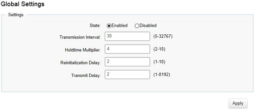
Select whether to enable or disable the LLDP feature on the switch. Next, enter the Transmission Interval, Holdtime Multiplier, Reinitialization Delay parameter, and the Transmit Delay parameter. When finished, click Apply to update the system settings.
- State: Select Enabled or Disabled to activate LLDP for the switch.
- Transmission Interval: Enter the interval at which LLDP advertisement updates are sent. The default value is 30. The range is from 5 to 32767.
- Holdtime Multiplier: Enter the amount of time that LLDP packets are held before packets are discarded and measured in multiples of the Advertised Interval. The default is 4. The range is from 2 to 10.
- Reinitialization Delay: Enter the amount of time of delay before reinitializing LLDP. The default is 2. The range is from 1 to 10.
- Transmit Delay: Enter the amount of time that passes between successive LLDP frame transmissions. The default is 2 seconds. The range is from 1 to 8192 seconds.
The following can be configured under LLDP:
- Local Device: LLDP devices must support chassis and port ID advertisement, as well as the system name, system ID, system description, and system capability advertisements. Here, you can view detailed LLDP information for the switch.
- Remote Device: LLDP devices must support chassis and port ID advertisement, as well as the system name, system ID, system description, and system capability advertisements. From here you can view detailed LLDP Information for the remote device.
IGMP Snooping
Internet Group Management Protocol (IGMP) Snooping allows a switch to forward multicast traffic intelligently. Multicasting is used to support real-time applications such as video conferencing or streaming audio. A multicast server does not have to establish a separate connection with each client. It merely broadcasts its service to the network, and any host that wishes to receive the multicast register with their local multicast switch.
A multicast group is a group of end nodes that want to receive multicast packets from a multicast application. After joining a multicast group, a host node must continue to periodically issue reports to remain a member. Any multicast packets belonging to that multicast group are then forwarded by the switch from the port.
- IGMPv1: Defined in RFC 1112. An explicit join message is sent to the switch, but a timeout is used to determine when hosts leave a group.
- IGMPv2: Defined in RFC 2236. Adds an explicit leave message to the join message so that the switch can more easily determine when a group has no interested listeners on a LAN.
- IGMPv3: Defined in RFC 3376. Support for a single source of content for a multicast group.
The following can be configured under IGMP Snooping:
- Global Settings: Click to enable or disable the IGMP Snooping feature for the switch.
- VLAN Settings: Use the IGMP Snooping VLAN Settings to configure IGMP Snooping settings for VLANs on the system.
- Querier Settings: IGMP Snooping requires that one central switch to periodically query all end devices on the network to announce their multicast memberships and this central device is the IGMP querier.
- Group List: The Group List displays the VLAN ID, group IP address, and members port in the IGMP Snooping list.
- Router Settings: The Router Settings shows the learned multicast router attached port if the port is active and a member of the VLAN. Select the VLAN ID you would like to configure and enter the Static and Forbidden ports for the specified VLAN IDs. All IGMP packets snooped by the switch will be forwarded to the multicast router reachable from the port.
Click Apply
 to accept the changes or Cancel
  to discard them.
MLD Snooping
Multicast Listener Discovery (MLD) Snooping operates on the IPv6 traffic level for discovering multicast listeners on a directly attached port and performs a similar function to IGMP Snooping for IPv4. MLD snooping allows the switch to examine MLD packets and make forwarding decisions based on content. MLD Snooping limits IPv6 multicast traffic by dynamically configuring the switch port so that multicast traffic is forwarded only to those ports that wish to receive it. This reduces the flooding of IPv6 multicast packets in the specified VLANs. Both IGMP and MLD Snooping can be active at the same time.
The following can be configured under MLD Snooping:
- Global Settings
- Status: Select to enable or disable MLD Snooping on the switch. The default setting is Disabled.
- Mode
- IP: Group List will be changed to IP mode, and switch will learn group by MLD join packet’s IP address.
- MAC: Group List will be changed to mac mode, and switch will learn group by MLD join packet’s MAC address.
- Report Suppression: Select either Enabled or Disabled. This feature limits the amount of membership reports the member sends to multicast capable routers.
- VLAN Settings: If the Fast Leave feature is not used, a multicast querier will send a GS-query message when an MLD group leave message is received. The querier stops forwarding traffic for that group only if no host replies to the query within the specified timeout period. If Fast Leave is enabled, the switch assumes that only one host is connected to the port. Therefore, Fast Leave should only be enabled on a port if it is connected to only one MLD-enabled device.
- Querier Settings: IGMP Snooping requires that one central switch to periodically query all end devices on the network to announce their multicast memberships and this central device is the IGMP querier. The snooping switch sends out periodic queries with a time interval equal to the configured querier query interval. The IGMP query keeps the switch updated with the current multicast group membership information. If the switch does not receive the updated membership information, then it will stop forwarding multicasts to specified VLANs.
- Group List: The Group List displays VLAN ID, group IP address, and members port in the MLD Snooping list.
- Router Settings: The Router Settings shows the learned multicast router attached port if the port is active and a member of the VLAN. Select the VLAN ID you would like to configure and enter the Static and Forbidden ports for the specified VLAN IDs. All MLD packets snooped by the switch will be forwarded to the multicast router reachable from the port.
 to accept the changes or Cancel
  to discard them.
Multicast Filtering
When Multicast Filtering is enabled, unknown multicast packets (did not learn by IGMP and MLD) will be dropped, and the multicast packets already learnt by IGMP/MLD will forward as multicast forwarding table. When Multicast Filtering is disabled, unknown multicast packets (did not learn by IGMP and MLD) will be flooded, and the multicast packets already learnt by IGMP/MLD will forward as multicast forwarding table.
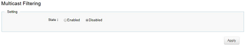
- State: To set Multicast Filtering as Enabled or Disabled. Default is disabled.
Click Apply to update the system settings.
Jumbo Frame
Ethernet has used the 1500-byte frame size since its inception. Jumbo frames are network-layer PDUs that have a size much larger than the typical 1500-byte ethernet Maximum Transmission Unit (MTU) size. Jumbo frames extend ethernet to 10240 bytes, making them large enough to carry a 10 KB application datagram plus packet header overhead. If you intend to leave the local area network at high speeds, the dynamics of TCP will require you to use large frame sizes. The switch supports a jumbo frame size of up to 10240 bytes. Jumbo frames need to be configured to work on the ingress and egress port of each device along the end-to-end transmission path.
Furthermore, all devices in the network must also be consistent on the maximum jumbo frame size, so it is important to do a thorough investigation of all your devices in the communication paths to validate their settings.
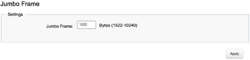
- Jumbo Frame: Enter the size of jumbo frame. The range is from 1522 to 10240 bytes.
Click Apply to update the system settings.